A retrospection of my Lego work, including new works and some clock future projects.
This part will explained the last attempts to create a clock.
I have started again to create clock in 2013, the aim was to build a new clock with more accuracy, more energy saver, more autonomy. Also, I have tried many concepts including some elements from the Great Ball Contraption and new mechanical remontoir likes wind-up motor.
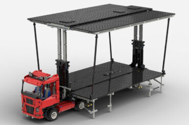
The Great Ball Contraption Idea
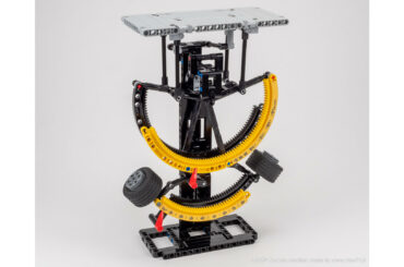
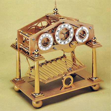
In august, by researching ideas for clock, I found a new idea : congreve clock. Its functioning is based on a ball which rolls on a inclined plan. Each time the ball has reached the left or the right side, the plan is raised and the ball continues its way from the other side.
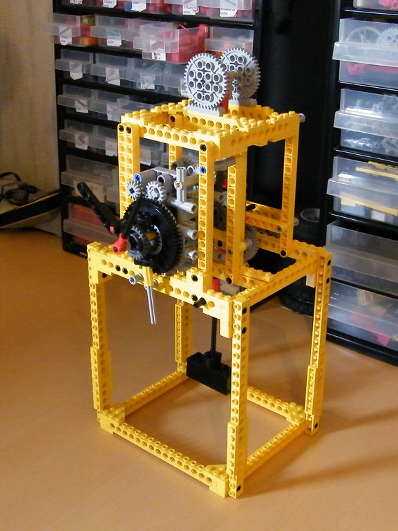
I have built a replica for testing the idea. I have used a simple wind-up motor to drives the clock with a inertia fan to have a smooth functioning. The ball rolls on a simple inclined plan, and on each side, the ball pushes a connecting rod which releases a cog connecting to the motor and the inclined plan. I didn’t make picture about it, only a video :
Finally the concept was interesting but the clock was not reliable and has not enough autonomy. I have failed to create a long inclined plan with enough force to the ball for pushing the connecting rod. Reproduce the tortuous shape was difficult.
Simple Enhanced Clock – Pendulum
Therefore, I have tried to build a simple clock with enhanced functioning. I would like to enhance the autonomy by reducing the whole friction in the functioning, improve the energy saver, try more pendulums and escapement systems to have a better Q factor (which quantify the performance of pendulum-escapement system.
The first thing I have tried is the system of bearing on the pendulum. I have tried a gear on a rack pinion, instead of a normal axle. By reducing the weight on multiple tooth despite on an axle, the performance was better and the Q factor too. But the center of the rotation of this system is not a fixed axle, the axle moves slightly from left to right which decreases the stability and the reliability of the system. Nevertheless, this system is even better than normal axle pendulum.


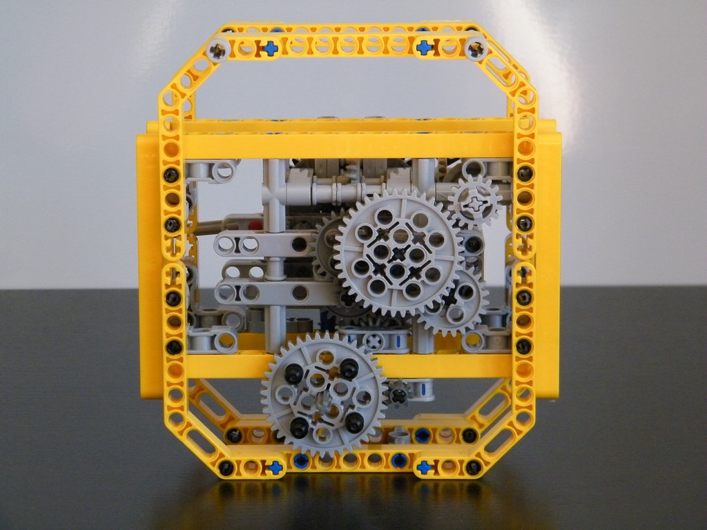
Simple Enhanced Clock – Escapement
To finish I would like to keep the system of pendulum with the rack pinion and work on the escapement system, which is a big part of energy loss in a clock. That is why I have made a second prototype with a particular MacDowall escapement system.
I have been inspired by this fantastic video of the Macdowall escapement :
You can see here the only prototype of this 1850′ escapement :

The advantage of this escapement is that the pendulum is not forced to move during its movement, when it has finished to move on the left or on the right, the escapement system only maintain the movement. Nevertheless this system has a bad autonomy because it makes one revolution for one period of pendulum so a ratio of 1:1. The ratio for the second escapement was 1:4 (4 pins on 40 teeth).
I have not made a video but pictures :


But the functioning was not very reliable, due to the escapement system, the force tends to lift the pendulum, and as it is not attached and just put on, it tends to lift and sometime miss a tooth.
This attempt closes my work on 2013 clocks. The last clock I build will be presented soon with its own article, and is very far from I have ever build.