
A Continuously Variable Transmission (CVT) with mechanical tachometers.

This CVT was based on Zblj’s works. It enables a variable ratio on the output from 1:1 to 1:5. The CVT chooses the most suitable ratio functions of the resistive torque on the output. The principle is based on two differentials which are connected side by side with a first gear : 1:1 and a second gear on the other side : 1:5. The side with the 1:5 gear has also a friction pin in order to limit the rotation.
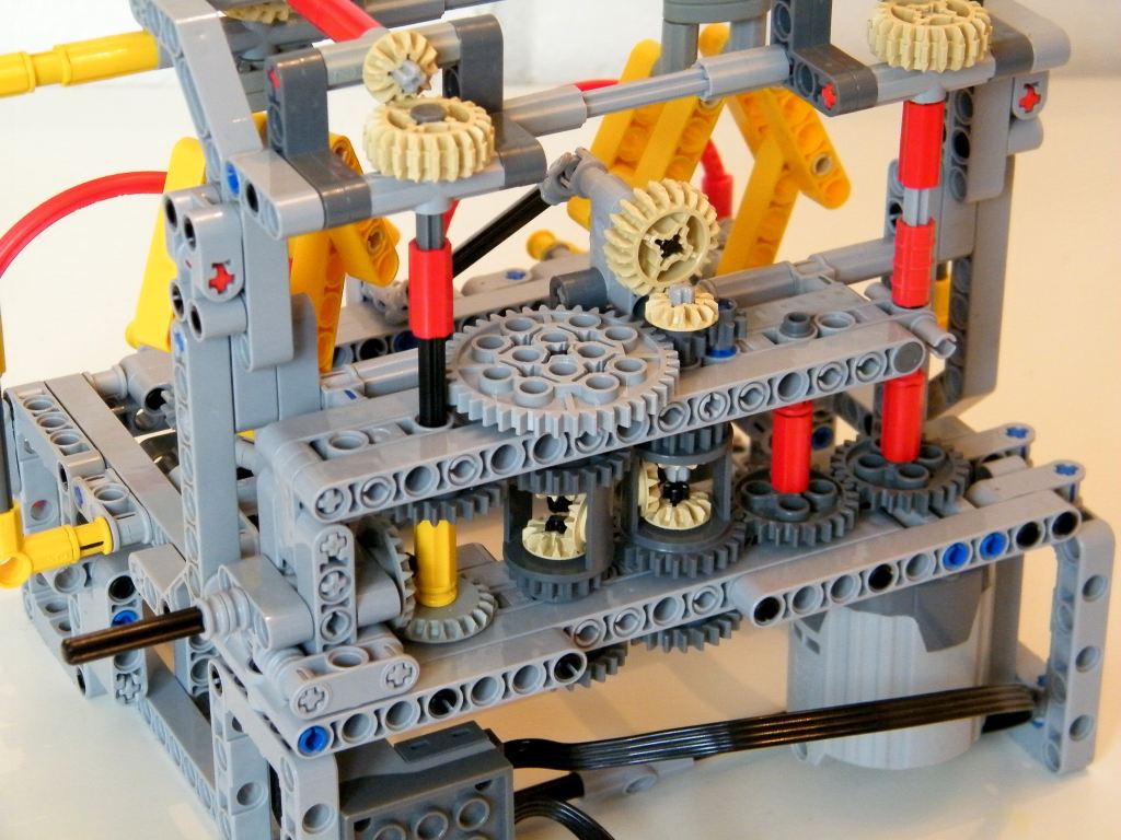
While there is not resistive torque (or low), the rotation goes through by the 1:1 gear because the 1:5 has locking torque thanks to the friction pin. When a torque is detected, the friction pin starts to spin and the rotation goes through the 1:5 gear which reduces the speed and increases the torque, the speed of the motor remains constant.
The two mechanical tachometers are not useful for the functioning of the CVT, they are useful to visualise the instantaneous speed of the motor (on the left) and of the output (on the right). Of course when the torque become too high, (around more than 5x motor torque), the speed of motor is reduced.
This CVT enables to have :
- A constant speed of the motor (200 rpm)
- A infinity of variable ratio between 1:1 and 1:5
- A variable speed between 200rm (1:1) and 40 rpm (1:5)
- A variable torque between 50N.cm (1:1 = motor torque) and arround 250N.cm (1:5)
Of course, some torque are lost because of the friction pin but the torque is increased by 5 so the loss is negligible regarding the increase.


Here is some pictures in order to re-built it :


(16) Comments
The building instructions are really simple to understand, there are not back-parts and hidden thing. the construction is simple and efficient, so keepup the good work and try and re-try !
This is a video.
maybe a video?
Can you put out a little bit of better and easier to understand instructions? Awesome model by the way.
Thank you ! A little bit hard to understand, do you have some pictures or rendering of your idea ? Regards
If you’re interested, there is a way to construct a continuously variable transmission without a friction pin, with a gear ratio which varies smoothly between 1:1 and 1:infinity.
First, construct a pair of double-acting ratchets. When the input shaft of either ratchet is rotated either clockwise or counterclockwise, the output shaft of the transmission is rotated forwards.
Next, construct a pair of power dividers. Each power divider is a Technic beam, with three gears on each side. On one side of each divider, the gears are 8 tooth, 24 tooth, 8 tooth. On the other side of each divider, the gears are 24, 8, 24. The four “outer” gears on each divider are connected to each other, in pairs, through the beam, with short axles. The central 8 tooth gear and the central 24 tooth gear are not directly connected to each other. The beam is supported by the axles passing through the two central gears, which each go almost halfway through the beam, but don’t quite touch each other. The beam extends some distance beyond the outer gears on one side.
Each of the ratchets has it’s input shaft connected to the central 24 tooth gear of one of the power dividers.
There are two identical flywheels. There are two approaches you can use for making the flywheels: Either made each from a solid plastic Lego wheel (no rubber tires), Or, make each from a beam and a pair of weights, or a panel and many weights. Each flywheel is connected to the central 8 tooth gear of one of the power dividers.
There is a crankshaft, driven by the electric motor. There are two cranks on the crankshaft. The cranks are 90 degrees apart from one another, so when one is vertical, the other is horizontal.
Each crank is connected to one of the power dividers by a Technic beam which acts as a connecting rod. The connecting rod attaches to the part of the beam which sticks out.
The cranks are long enough so that each rotation of the motor causes each power divider to oscillate once, through an arc of about 90 degrees.
That’s it!
—-
To observe the highest gear ratio (1:1) run the motor with no load on the output shaft. The flywheels will move very very little, and the output shaft will spin very quickly.
—-
To observe the lowest gear ratio (1:infinity) run the motor, with your hand very firmly holding the transmission output shaft. All of the motor’s power will go into accelerating the flywheels.
Mechanical energy will repeatedly move from one flywheel, through the power divider, through the crankshaft, through the other power divider, to the other flywheel, then back again.
The energy of each flywheel is proportional to it’s speed squared. This energy moves through the power dividers in the time it takes for the motor to rotate once. The power moving through either power divider needs to be braced against the ratchet, which transmits torque to the transmission’s output shaft.
Since energy equals speed times torque, the transmission’s output torque will be equal to the flywheel’s speed squared, times some constant.
Just in case it’s not obvious, the theoretical “infinite” torque multiplication only occurs when the motor reaches infinite speed. In reality, Lego motors have a finite (but fast) top speed, and thus the transmission produces a finite (but quite strong) torque.
—-
The transmission can be “tuned” by using heavier or lighter flywheels, or by chancing the gear ratio between the motor and crankshaft to something other than 1:1, or by changing the gear ratios on the power dividers, or by changing the arc through which the power dividers oscillate.
Doubling the crankshaft speed doubles the maximum output shaft speed, and quadruples maximum torque.
Doubling the weight of the flywheels doubles the maximum torque, but doesn’t improve maximum speed.
Swapping all six of the 24 tooth gears on the power dividers for 40 tooth gears increases maximum torque, but doesn’t improve maximum speed.
—-
Knowing what I do about Lego motors, I can say that in most circumstances, peak performance will occur if your transmission is adjusted so that the motor is usually spinning at close to one half of it’s maximum RPM.
Hi,
I love your transmission, and I did learn something from it. But I have to add that it cannot increase torque from the motor to the output. To see this, first notice that the essence of a differential is that under any circumstances, the torque on its two outputs is exactly half of the one on its input. Thus the grey gear at the right hand-side on the bottom has precisely half the torque of the motor, no matter what happens with the friction pin. That same half torque is then transmitted to the bottom-left grey gear, the double of which in turn gets transmitted to the output via the second differential. So at the end we arrive to output torque = input torque * 1/2 * 2 = input torque.
What happens is indeed that the excess power (that comes as the difference between input and output of the same torque but different rpm) is eaten up by the friction pin.
Also, if you increase the torque on the output side, I don’t think the 1:5 rpm ratio keeps maintained. Rather, the lower grey gears start to spin in reversed direction, and the output further slows down until it comes to a full stop. You could actually prevent this by applying a flywheel on the lower grey gears.
To summarize, I think your machine is a friction-based speed reductor, still of essential use in small motorcycles or even diesel locomotives. To overcome the problem of the binary effect you mentioned (friction pin either rotates or not), you could replace the friction pin by something with a more complex characteristics. Once I had an air resistance brake on the cables of a lego elevator: it had a fastening gear ratio and then a wheel with large flaps that were braked by pure air resistance. It could prevent the elevator from diving into the deep very fast in case my son lost control of the handles. 🙂 The faster the elevator descended, the more braking torque from air resistance it applied. Or you could use a mechanism similar to your tachometers to add more friction at higher rpms. Any of these instead of the friction pin would add smoother characteristics to your transmission I guess.
Sorry, I don’t have. Regards
Hello, I want to build it too!
Can you tell me what is the name of the box parts to make it ?
Thankyou.
André
Hello
is it possible to put this great builing into a car and use it like a gearbox…?
Thx
You are right ! In fact when the friction pins rotate, some power are lost but the torque is really increased (by 5) so I assume that the power is less lost than the torque is increased. I think for the vehicle application that torque is more importante in climbing that speed with power, of course power is speed * torque. The real problem with the CVT based on friction pin is that the friction pin is not enough resistant to overcome the necessary torque on the output so it is viable for small car but not for heavy drivetrain. Also the gearbox works a little bit binary (friction pin doesn’t rotate or rotates) and of course there are differences between rubbing and slipping regarding the fridtion coefficient. Not an easy subject !
Hey Nico.
First off, your models and website are truly excellent,you are without doubt one of my favourite lego builders, and I have learnt a lot from your stuff, so thanks for that. I do however have some queries about your CVT. I’m sorry if this comes across as negative, I felt the need to discuss these issues out of respect.
My point is that using friction as you have here does not lead to a what i would normally consider a CVT.
I accept that it is a ‘constantly variable transmission’ in terms of rotational speed but I believe that your CVT does not vary mechanical advantage like a normal gearbox would.
In a normal gearbox when you change, the power level remains the same. Changing down a gear you go from low force and high speed to high force and low speed. but all work done remains in the drivetrain.
With your CVT to change gear ratio the friction pin must rotate. For this to happen some work must be done to overcome the friction, as such some power is taken from the output. The more the ratio changes the faster the friction pin spins, and the more power is taken from the drivetrain. So when your gearbox ‘shifts’ down, all the mechanical advantage isn’t increasing, but power is being taken from the system to spin the friction pin.
I still think it’s an awesome build and really interesting, just not quite a true CVT.
Long may you continue to build!
Yes I think you could. The performance will not be the same at all.
Can I change the two 24t gears on the differentials to get
a different ratio? (Sorry for my english, I’m italian…)
Hello, thank you ! I have ever seen your website and have inspired me during the development of a CVT gearbox. Zblj is a slovenian builder.
Hi,
this is nice work. I have got a better understanding now of the friction based CVT’s. I realy like the tachographs. Now you need a controllable load for this demonstrator.
I will put a link to your cvt on my page as soon as possible. Who is Zblj? (He refers to me, and I don’t remember anymore)
regards,
Jurrien
Comments are closed.